Saturday, October 26, 2013

Arduino hardware with AVR Studio and coding in C or ASSEMBLY - no programmer required

Hi

Recently I was working on an IR recorder for my home automation projects. After working with Arduino and C, finally had to move to assembly since every single Atmega328 intruction was to be accounted for. The work is still on but I am very happy with results and what I have learnt about the hidden capabilities of Atmega328 waveform generation. That will be next time but I would like to  explain how I have used the Arduino hardware (Atmega328 with duemilanove bootloader) to be programmed from AVR studio using the bootloader and bypassing a programmer.

I had two main requirements as mentioned below:-

1) Write Code in assembly and generate Hex code. Download Hex code to Atmega328 and run.
2) Start a serial monitor at the end of program download since the code was designed to communicate with a terminal for configuration and passing the results (VT100 terminal emulation supported in the code).

Sponsor: www.avmicrotech.com/shop eshop for your electronic needs


To be able to use the Arduino hardware with AVRStudio, first  you will have to download avrdude from sourceforge and then  have to write a batch file in your AVRStudio project folder where the Hex file is generated. The batch file contents are as below.
--------------------------------------------------------------------------------------
ECHO OFF
ECHO Starting Avrdude please wait......
avrdude -P com30 -b 57600 -p m328p  -c arduino -F -e -U flash:w:AutoProg.hex
pause
--------------------------------------------------------------------------------------

Note:- You will have to change those in red as per details below.

com30 - This is the com port that your arduino UNO or deuemilanove shows up as
57600 - Downloading baud rate for duemilanove. For UNO it should be 115200 (please check).
m328P - For atmega328p. For Mega this will change. Please read the avrdude manual.
AutoProg.hex - This is the hex file that will be generated in your project folder hence you will have to change it as per your project name.

Imp:- If you get "not in sync" error msg during avrdude (Arduino) download, please update your avrdude to the latest version.

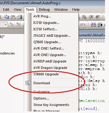
To down load the hex you will have to click (execute) this batch file in the folder alternatively you can also create a short cut in AVRstudio using Tools -> customize -> Tools. The screen shots are as below:-


This is how it appears in the AVRStudio menu.


The avrdude also releases the serial port after the download, hence the serialmonitor can be started immediately.

For a free serial monitor like Hyperterminal , you can download PUTTY and enable serial mode.

This is how I have been working for many years. If you know a shorter and better way then do let me know. Thanks!!
 

Wednesday, May 1, 2013

Raspberry Pi Direct USB to UART using FT232RL and Zigbee


Raspberry Pi Direct USB to UART for Zigbee communication.

I could not find complete information about using FT232RL USB to UART on the internet hence decided to put everything in writting.


Use the following information from FTDI website to install and check the FT232RL drivers


Sponsor: www.avmicrotech.com/shop  eshop for your electronic needs


**********************************************************

D2XX for Linux
--------------

As Linux distributions vary these instructions are a guide to installation 
and use.  FTDI has tested the driver and samples with Ubuntu 12.04 (kernel 
version 3.2) for i386 and x86_64, and Debian 6 'squeeze' (kernel version 
2.6.32) for arm926.

FTDI developed libftd2xx primarily to aid porting Windows applications 
written with D2XX to Linux.  We intend the APIs to behave the same on
Windows and Linux so if you notice any differences, please contact us 
(see http://www.ftdichip.com/FTSupport.htm).

FTDI do not release the source code for libftd2xx.  If you prefer to work
with source code and are starting a project from scratch, consider using
the open-source libFTDI.

libftd2xx uses an unmodified version of libusb 
(http://sourceforge.net/projects/libusb/).  Source code for libusb is 
included in the driver distribution.


Installing the D2XX shared library and static library.
------------------------------------------------------

1.  tar xfvz libftd2xx1.1.12.tar.gz

This unpacks the archive, creating the following directory structure:

    build
        arm926
        i386
        x86_64
    examples
    libusb
    ftd2xx.h
    WinTypes.h

2.  cd build/arm926

3.  sudo -s 
  or, if sudo is not available on your system: 
    su

Promotes you to super-user, with installation privileges.  If you're
already root, then step 3 (and step 7) is not necessary.

4.  cp lib* /usr/local/lib

Copies the libraries to a central location.

5.  chmod 0755 /usr/local/lib/libftd2xx.so.1.1.12

Allows non-root access to the shared object.

6.  ln -sf /usr/local/lib/libftd2xx.so.1.1.12 /usr/local/lib/libftd2xx.so

Creates a symbolic link to the 1.1.12 version of the shared object.

7.  exit

Ends your super-user session.

     ---I did not spent time on below----

Building the shared-object examples.
------------------------------------

1.  cd examples

2.  make -B

This builds all the shared-object examples in subdirectories.

With an FTDI device connected to a USB port, try one of the 
examples, e.g. reading EEPROM.

3.  cd EEPROM/read

4.  sudo ./read

If the message "FT_Open failed" appears:
    Perhaps the kernel automatically loaded another driver for the 
    FTDI USB device.

    sudo lsmod

    If "ftdi_sio" is listed:
        Unload it (and its helper module, usbserial), as follows.

        sudo rmmod ftdi_sio
        sudo rmmod usbserial

    Otherwise, it's possible that libftd2xx does not recognise your 
    device's Vendor and Product Identifiers.  Call FT_SetVIDPID before
    calling FT_Open/FT_OpenEx/FT_ListDevices.


Building the static-library example.
------------------------------------

1.  cd examples/static

2.  rm lib*

Cleans out any existing libraries built for another target.

3.  cp /usr/local/lib/libftd2xx.a .

4.  make -B

5.  sudo ./static_link

This example demonstrates writing to, and reading from, a device with
a loop-back connector attached.


The examples show how to call a small subset of the D2XX API.  The full
API is available here:
http://www.ftdichip.com/Support/Documents/ProgramGuides/D2XX_Programmer%27s_Guide(FT_000071).pdf

-----------End of skipped portion---------
***************************************************************


Sponsor: www.avmicrotech.com/shop  eshop for your electronic needs


Now check if your FTDI drivers have loaded properly. Insert your FTDI board into raspberry pi USB port and enter the command dmesg on Raspberry pi terminal. If you see this output at the end, you have your USB to UART, FT232RL installed.

[ 3194.136661] usb 1-1.2: Product: FT232R USB UART
[ 3194.136675] usb 1-1.2: Manufacturer: FTDI
[ 3194.136687] usb 1-1.2: SerialNumber: AH001BVN
[ 3194.188124] usbcore: registered new interface driver usbserial
[ 3194.190895] usbcore: registered new interface driver usbserial_generic
[ 3194.192574] USB Serial support registered for generic
[ 3194.192618] usbserial: USB Serial Driver core
[ 3194.207107] usbcore: registered new interface driver ftdi_sio
[ 3194.209875] USB Serial support registered for FTDI USB Serial Device
[ 3194.210233] ftdi_sio 1-1.2:1.0: FTDI USB Serial Device converter detected
[ 3194.210754] usb 1-1.2: Detected FT232RL
[ 3194.210781] usb 1-1.2: Number of endpoints 2
[ 3194.210797] usb 1-1.2: Endpoint 1 MaxPacketSize 64
[ 3194.210812] usb 1-1.2: Endpoint 2 MaxPacketSize 64
[ 3194.210826] usb 1-1.2: Setting MaxPacketSize 64
[ 3194.212075] usb 1-1.2: FTDI USB Serial Device converter now attached to ttyUSB0
[ 3194.212192] ftdi_sio: v1.6.0:USB FTDI Serial Converters Driver

Now testing time........

Please note that FT232RL  baud rate is that of the Xbee module's UART interface. I have both my Zigbee set at 115200. Hence data going out from FT232RL should be at 115200.

Option 1:- Add minicom program on raspberry pi and X-CTU Terminal on your PC. Please do not forget to configure both minicom and X-CTU to Hardware Flow control to "No".


minicom -b 115200 -o -D /dev/ttyUSB0

Alternatively you can configure minicom using

minicom -s


You exit minicom by typing first ctrl A   then Z and X (without ctrl).

Option 2:-Use the python code as mentioned in this link   http://elinux.org/Serial_port_programming. You will have to change your serial port to ttyUSB0. On PC side use X-CTU Terminal.

import serial

port = serial.Serial("/dev/ttyAMA0", baudrate=115200, timeout=3.0)
port = serial.Serial("/dev/ttyUSB0", baudrate=115200, timeout=3.0)
while True: port.write("\r\nSay something:") rcv = port.read(10) port.write("\r\nYou sent:" + repr(rcv))

This code too does a round trip data flow hence test both direction communication.


Sponsor: www.avmicrotech.com/shop  eshop for your electronic needs


.....cont

Saturday, April 27, 2013

Raspberry Pi Zigbee for Wireless puTTY communication

As part of the robotics project, decided to use Zigbee instead of physical UART / LAN cable to make a wireless Raspberry Pi.. Not much information is available on Raspberry Pi interfacing with PC through Zigbee, maybe it is because the system is very simple. Below is the picture of a wireless Raspberry Pi that can be controlled from half a kilometer away.


Sponsor: www.avmicrotech.com/shop  eshop for your electronic needs


One of the main advantage of above hardware is that it uses the 5V to 3.3V regulator on board the Zigbee board and hence does not load the meager 50mA 3.3V of Raspberry pi. I am still using puTTY (at serial 115200) to control the raspberry pi. Below is snapshot while editing code wirelessly.


Used X-CTU to configure Zigbee Pro to 115200 baud.


Raspberry Pi H Bridge DC motor driver


As we all know, the Raspberry Pi has powerful computing power. In order to put these to use, I am planning to develop a vision based Robot. Maybe a vision based line follower. The first step was to develop locomotion. I am always in favour of using optoisolated boards for DC motor drive, as high inductance and commutation produce a good amount of noise in the circuit.


Sponsor: www.avmicrotech.com/shop  eshop for your electronic needs


 In this trial, I have used a SPI controlled Attiny2313 based board producing 100hz PWM (configurable from 100Hz to 700Hz). The board need 7 bytes to configure all the parameters of the two DC motors like PWM (speed), direction and frequency. The SPI frequency is 25000Hz. The code on Raspeberry Pi is slightly modified spidev_test.c The motor driver board is running off the Raspberry PI 3.3V which is limited to 50mA. My estimate is worst case scenario of less than 30 mA.


Sunday, April 7, 2013

Raspberry Pi PuTTY Xming GPIO WebOb Python

Below is my experience from 2 days of tinkering with Raspberry Pi.

Purchased: Raspberry Pi 500MB with cover Plus 4GB preloaded SD card from Farnell.


Day 1.
Connected with 42" LCD TV and though Bootup took some time but was able to complete all without any problem.  Installed Putty and Xming on my laptop to free the LCD TV. In 2 hours my Raspberry Pi was setup near my router remotely connected to my laptop.
Decided to move from 4GB to 8GB and a faster Raspberry Pi using class10 SD card. Purchased a SanDisk Ultra 8GB - SDSDQUA-008G-U46A class 10 SD card. Though a website mentioned it as incompatible, went ahead to install the latest image downloaded from Raspberry Pi downloads  using Win32DiskImager. Used samsung laptop SDcard reader to transfer image to the SD card. First Install had problem communicating with PuTTY as maybe full startup was not done during first boot and SSH key was not generated. Second image flashing worked perfectly.
Before starting PuTTY, first get the IP address of Raspery Pi using the command ifconfig. Logon using PuTTY and click start Xming. Type Startlxde at PuTTY to start the GUI window on Xming.


Sponsor: www.avmicrotech.com/shop  eshop for your electronic needs


Day 2.
 Full code testing time today. Raspberry Pi Educational Manual is excellent for novice like me. But some issues are not reported like Pygame not available yet with Python3. So the first thing is to do some update and install some packages.

You will need these
To get all the needed updates you need to execute these commands at LXterminal:-

$ sudo apt-get update

To get Python updates
$ sudo apt-get install python-dev

To install GPIO that is used in the example in Raspberry Pi educational manual
$ sudo apt-get install python-rpi.gpio

To install WebOb that is used in the example in Raspberry Pi educational manual
$ sudo apt-get install python-WebOb


.....cont


Saturday, March 9, 2013

From VB6 to .Net ( VB2010 )


After coding in VB6 for over 15 years, finally decided to move to VB2010.  As before, the project was already on hand and it was my last minute decision to move to .Net. I could have downloaded a trial version of VB2010 few years before and played with it, but with many different projects running simultaneously time was always short and that never happened.

I am not a pure software person, all my projects are more of hardware than software part. Software is only limited to GUI, Database, proprietary bus interface and data exchange with factory automation system.


Sponsor: www.avmicrotech.com/shop  eshop for your electronic needs


My first impression was total betrayal as I seemed to be programming in Visual C++  than VB. Common ActiveX like winsock was not available by default in Vb2010. Message read from serial port could not be written directly to Textbox.... different threads. As TCP/IP was to be used for data exchange with Host, I had to re-write the communication backbone which was not an ordinary ASCII stream but a complex system that was optimised for engineering data exchange. I had to transfer variables stored as Integer, single and double to byte stream of unsigned integer, 4byte floating point and 8 byte floating point.

But after 3 weeks of coding I was more than happy. It was very easy to come up with multi-threaded system where the data exchange with host was running independently from my user interface and background data collection part. Further all my data conversion were handled by native functions  Overall a much simpler and compact than my previous projects.

....cont

Friday, March 8, 2013

Arduino UNO Bootloader and Firmware


Arduino UNO by design has come out be a complex system, needing three different flash programs to make it run. I will show where these three are located and method to update them. Below excerpt is from Atmega8u2 /Atmega16u2 datasheet.


When the HWBE fuse is enable the PD7/HWB pin is configured as input during reset and sampled during reset rising edge. When PD7/HWB pin is ‘0’ during reset rising edge, the reset vector will be set as the Boot Loader Reset address and the Boot Loader will be executed .


Hence starting with Atmega8u2 / Atmega16u2 that is used as USB to UART, when it is first connected to the USB port of your PC, it is read as power on by the Atmega8u2 / Atmega16u2 and bootloader is skipped and it enters application section (i.e usb to uart) even though your HWB pin is pulled low (for UNO Rev3). However if you reset Atmega8u2 / Atmega16u2 it is read as reset by the uC and during the rising edge of reset signal the uC enters into the bootloader mode.


Sponsor: www.avmicrotech.com/shop   eshop for your electronic needs


So below are the configuration to flash different parts of devices on UNO

Device Section SourceMethod
Atmega8u2 / 16u2 Bootloader usbdfu Through ISP Header at top right
Atmega8u2 / 16u2 Application Section usbserial Reset Atmega8U2 by shorting reset to gnd to enter bootloader.
Atmega328 Bootloader Optiboot Through ISP Header at the bottom

Actually, the usbdfu and usbserial  are combined together in Arduino distribution as 1 hex file and can be downloaded in one go though Atmega8u2 /  Atmega16u2 6 pin ISP port and using AVR ISP.

.....cont


Wednesday, March 6, 2013

Arduino : Difference between UNO and Duemilanove bootloader


Some of the difference are very well known like smaller bootloader size, faster flash programming by UNO, replacement of FT232RL with Atmega8u2, however I would like to explore more on the technical and implication part.
1) EEPROM write- This will be missed as I would in many cases write configuration data in eeprom like calibration file etc. Though eeprom can always be updated through user code.


Sponsor: www.avmicrotech.com/shop eshop for your electronic needs


2) Adaboot no wait mode: This might have been added later in duemilanove, but it needs special mention.This is a check in bootloader to know the source of reset and react accordingly.Hence if uC enters bootloader due to watchdog reset or brown out reset it immediately leaves bootloader and jumps to main program.Hence other than hardware reset your uC will never enter bootloader.
3) Watchdog handling: The UNO bootloader has code to handle the watchdog timer if it is activated by setting WDTON in Fuse High Byte in your project. In older version the Arduino will stay in bootloader forever if WDT was enabled.

In addition to above some unnecessary zero initialisation commands are removed to save code space.

Hardware differences

1)On older boards, the FT232RL was also providing a free 3.3V output. In the UNO, a separate LP2985 LDO regulator produces 3.3V at 150mA DC from internal 5Volts.


2)The 16Mhz Crystal oscillator for Atmega328 is replaced with 16Mhz resonator (UNO Rev 3).

Board Reliability improvement upgrades

1)The UNO rev3 finally has diode to clamp reset pin voltage to 5Volts.

2)All UNO have varistor protection for USB D+ / D- signal lines. To prevent voltage spike destroying the Atmega16U2.


......cont


Arduino : My Learning Journey


I have been using Arduino from the time it first appeared in the market. Before  that I was using AVR studio / stk500 with Atmega8 and Atmega168. Atmega328 had not arrived yet. STK500 was a good prototyping platform where most of the AVR features like fuses could be set or reset. My first trial was to make and download the Arduino bootloader into an Atmega8, but due to some issue it kept failing which I soon  realised was due to the code compiling into a size bigger than the Atmega8 bootloader. I had no choice but to go debug the code and remove some redundant commands and finally was able to squeze in the code. I got two additional benefits from this study first I was able to reduce the bootloader delay to 1 sec and second I could enable the watchdog timer handling in the bootloader....


Sponsor: www.avmicrotech.com/shop eshop for your electronic needs


Watchdog

A micro-controller latch-up (hang) on a production machine is biggest nightmare for any hardware designer as this small insignificant event can cause unnecessary stoppage and activation of technicians. I was also bitten by the same fear when adding a uC (micro-controller) to carry out BCD to serial conversion in one of my projects. The uC latch-up would have resulted in bad reputation. I found a very unconventional solution. A watchdog was setup for a few seconds and nothing was done to handle it. so the system would automatically reset after a few seconds which was seamless to the operation. The system worked so flawlessly and thanks to Cygnal (now Silicon Labs) uC reliability, I have system running untouched for over ten year!!


Sponsor: www.avmicrotech.com/shop eshop for your electronic needs


Wiring or C

Recently I was requested by one of the faculty member of an Engineering college in New Delhi to setup some experiment for their embedded lab around Arduino Hardware. They were very surprised and happy when I configured  AVR studio to download compiled C programs directly to an Arduino board. With this the students could learn to program in real C or C++ using winavr and later use rich Arduino Libary to interface complex hardware like SD card or Ethernet controller.
I am of the opinion that Engineering students should retain and develop their C skills and at the same time learn  ARM processor. The cost of  ARM devices have dropped and boards are available at prices slightly higher than Arduino. I am seeing that engineering students at NUS Singapore directly start hardware programming on NXP arm boards in C and assembly (inline).

......cont